Chapters
- 1 Getting started
- 2 The interface
- 3 Coordinate systems and conventions
- 4 Modelling
- 5 Materials
- 6 Sections
- 7 Supports, releases and modifiers
- 8 Loads
- 9 Load combinations
- 10 Meshing
- 11 Static analysis
- 12 Dynamic and seismic analysis
- 13 Results
- 14 Design
- 15 Scripting and the AI model builder
- 16 Import and export
- 17 Verification
- 18 Scope and limits
- 19 Troubleshooting
- 20 Glossary and notation
On this page
A frame section gives a member its area, second moments of area, torsion constant, shear areas and shape; an area section gives an area its type and thickness. The FEA Tool takes frame sections from the steel libraries of four code regions, from parametric forms, from a section designer for steel, reinforced concrete and composite members, and from a drawing canvas on which any section is drawn with the cursor. This chapter covers each source, the properties computed, auto-select lists and area sections.
6.1 Section properties used by the analysis
The frame element reads these properties of a section, in its local axes (Section 3.2):
| Property | Symbol | Use |
|---|---|---|
| cross-section area | axial stiffness, self weight, mass | |
| shear areas along 2 and 3 | , | shear deformation; zero turns it off for that direction |
| torsion constant | Saint-Venant torsional stiffness | |
| second moments of area | , , | bending stiffness about the major and minor axes |
| warping constant | design modules; not used by the frame element | |
| elastic and plastic moduli | , , , | stresses, plastic hinges, design |
The section table of the form lists 13 properties with the mass per metre: , , , , , , , , , , , , .
6.2 Section libraries
Model > Code libraries holds the steel sections of each region: AS (AS/NZS 3679.1 and AS/NZS 1163 hot rolled, welded and hollow sections), US and CA (the AISC Shapes Database in US and CSA names), and EU (EN 10365, EN 10210-2 and EN 10056: IPE, HE, hollow sections and angles). Type in the search box, filter by shape, pick a section and press Assign section to give it to the selected members.
Names are matched without regard to spaces and punctuation, so 310UB40.4 and 310 UB 40.4 are the same section, as are HEA200, HE200A and HE 200 A. A section found only in another region's library is accepted and the properties panel says so, for example that IPE 300 is a European section in an Australian model; change the design code or pick a local section before you design.
For AS sections, the torsion constant, minor-axis moduli and shear areas are computed from the plate dimensions of the section.
6.3 Sections from a name
A section name that describes a solid or a timber size is read directly:
| Name | Section |
|---|---|
300x500RC, R300x600 | concrete rectangle 300 mm wide and 500 (600) mm deep |
400x400RC col | concrete rectangle with the column role |
D450, 450 dia RC | concrete circle of 450 mm diameter |
90x45MGP10 | timber rectangle of the named grade |
C600 | circle of 600 mm diameter |
For a name without an orientation, the larger dimension is the depth (along local 2).
6.4 Parametric frame sections
Model > Frame sections defines a section by its shape and dimensions. The shapes are rectangle, circle, I (with unequal flanges), box, pipe, channel, angle, double angle, tee, general (properties typed in) and library. The form shows a sketch with the local axes 2 and 3, the 13 properties and the mass, and keeps a colour and notes with the section. Save section adds it to the model, Save and assign to the selection gives it to the selected members.
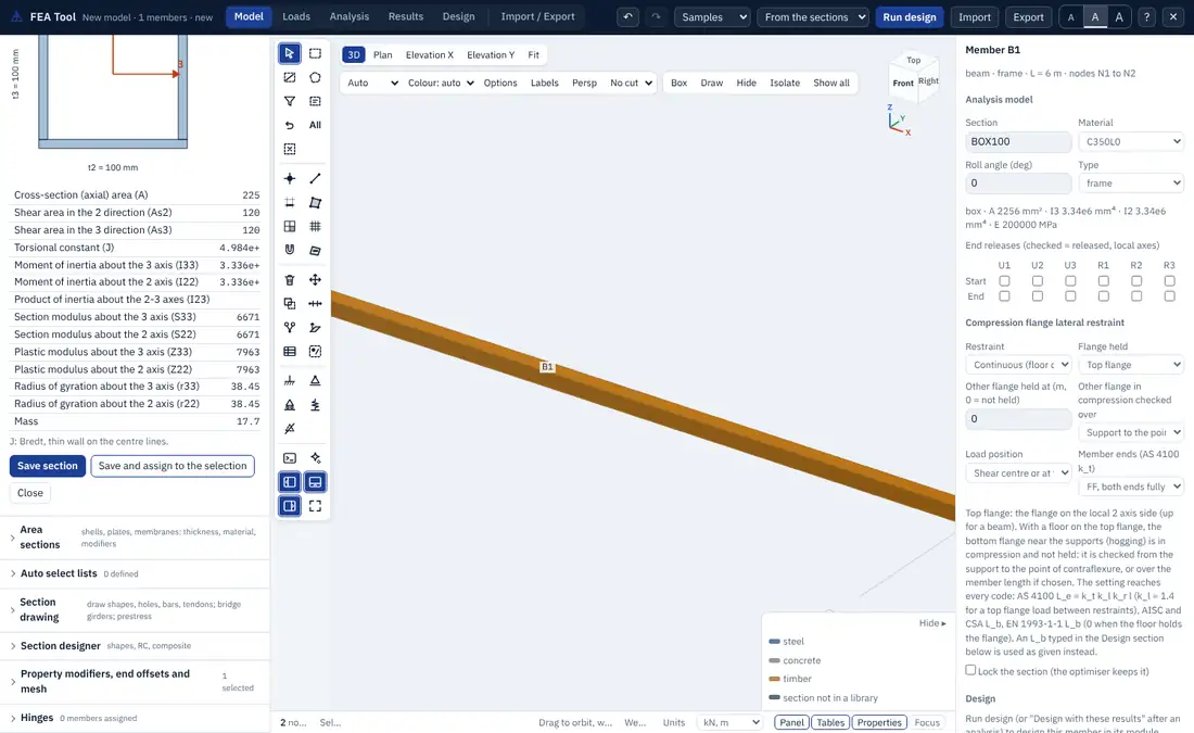
Torsion constant. For a solid rectangle of depth and width with , the form uses the Saint-Venant series (Timoshenko and Goodier):
Solids read from a section name (such as R300x600) use the close approximation of Roark (Table 10.7, case 4):
For a thin-walled closed section (box, pipe) the Bredt formula is used on the centre line of the wall,
with the area enclosed by the mid-line of the wall and the wall thickness. For an open thin-walled section, over its plates. The form states which rule it used.
Shear areas. The form computes the shear areas as follows:
| Shape | (along local 2) | (along local 3) |
|---|---|---|
| rectangle | ||
| circle | ||
| pipe | ||
| I, tee | of the flange areas | |
| channel | of the two flange areas | |
| box | ||
| angle | of the vertical leg | of the horizontal leg |
Concrete reinforcement. A concrete rectangle or circle can carry its reinforcement for the design: the role (beam or column), the clear cover to the ties, the bar diameter and count on each face (or around a circle), the top and bottom bars of a beam, the tie diameter and spacing, and ties or a spiral. The member design modules read these values; the analysis uses the gross section unless modifiers are set (Section 7.7).
6.5 Section designer
Model > Section designer builds a section from a parametric definition and computes its full set of properties, its cracked properties and its nonlinear response. The kinds are:
| Kind | Shapes and data |
|---|---|
| Steel | I (unequal flanges), channel, angle, tee, box, pipe, rectangle, circle, polygon |
| Reinforced concrete | rectangle, circle, T and L, with cover, ties, bars on each face or around a circle, extra bars, and confinement |
| Composite | a steel I beam with a concrete slab: effective width from the span and spacing by code, profiled deck (rib height, width and spacing, ribs across or along the beam), slab reinforcement, degree of shear connection, short or long term |
| Concrete-filled tube | a rectangular or circular steel tube filled with concrete |
| Encased | a steel section encased in reinforced concrete |
The properties include the centroid, , , , the principal moments of area and their angle, elastic and plastic moduli, the plastic neutral axis, , , the shear centre and the shear areas. For composite sections the transformed second moment of area is given for short and long term with the modular ratios, and the effective for partial shear connection. For concrete sections the cracked second moment of area is given for sagging and hogging, with the effective second moment of area of the code.
Stiffness for analysis. The section designer can set the stiffness the analysis uses: gross, the cracked-section factors of the code for beams, columns, walls and slabs, the cracked section, or the effective section. It writes the choice as property modifiers on the section, with a note of the basis.
Moment-curvature. The section is divided into fibres, each following the stress-strain curve of its material (Section 5.5). With stresses and strains positive in tension and for a chosen axial force, the curvature is increased step by step and the moment is found from equilibrium of the fibre stresses:
where is the position of fibre along local 2 and the axial strain at the reference point, found so that equals the given force. The curve marks the events: cracking, first yield, cover spalling, crushing, the ultimate concrete strain , the compression limit of the bars and bar fracture. A bilinear idealisation gives the first yield moment, the nominal moment, the yield and ultimate curvatures and the curvature ductility.
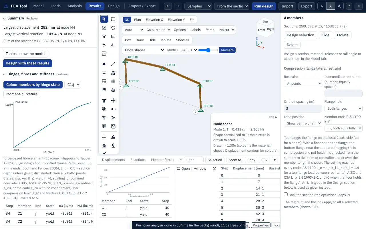
Interaction diagram. The P-M interaction curve is found by strain compatibility with the extreme fibre at and the rectangular stress block of the code, as nominal values without strength reduction factors, with moments about the centroid of the gross section. The squash load and the balance point are marked.
6.6 Section drawing
Model > Section drawing is a canvas on which a section of any shape is drawn with the cursor, in millimetres. Use it for bridge girders, precast units, built-up and composite sections, and sections with holes.
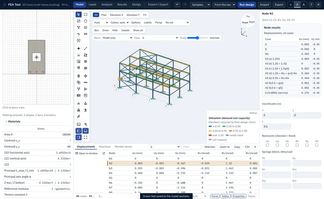
Tools. Select or move, pan, polygon, rectangle, circle, standard steel shape, bridge template, single bar, line of bars, perimeter bars and tendon. The wheel zooms and the middle button pans. Points snap to a grid (50 mm by default) and to the vertices of other shapes, and can be typed as x, y or @dx, dy. The drawing axes are local 2 up and local 3 to the right, seen from end of the member.
Bridge templates. I-girder, bulb-tee, box with one or more cells, closed or open trough, voided slab, and composite (a girder with a haunch and a deck cast in stage 2). A template stays editable through its parameters after it is placed.
Materials and holes. Every shape has its own material (concrete, steel, reinforcing bar, tendon or other) and a stage (1 or 2). A shape marked as a hole cuts the shapes below it.
Overlapping shapes. Shapes are resolved in drawing order. A solid joins the region of its own material and stage, cuts the regions of other materials below it, and a hole cuts every region below it. The panel names each overlap it resolved. Circles are drawn as 192-sided polygons, but a circle that no other shape cuts is integrated exactly.
Properties. The properties are given on a chosen basis: gross (bars left out), transformed short term, or transformed long term, about the reference material of the section. They include those of the section designer, the stage 1 section of a composite girder, the cracked section in sagging and hogging, and the totals of bars and tendons.
Saving. A drawn section is saved to the model's sections (and can then be assigned to members) or to a JSON section library that other models can read. In the 3D view a member with a drawn section is drawn with its true outline. The fibre tools of the section designer (moment-curvature and interaction) accept drawn sections unchanged.
6.7 Prestress
Tendons are placed on the drawing canvas by position (or by eccentricity), number of strands and strand area, with the jacking stress or force and the losses at transfer and in the long term, as percentages. The panel gives the prestress forces at jacking, transfer and service, the eccentricity of the tendon group, and the stresses at the top and bottom fibres at transfer and in service under the moments you give: the moment at transfer, the moment of the second-stage dead load, and the moments of the permanent and total service loads.
The fibre stress follows from the force at eccentricity below the centroid and the moment (sagging positive):
with measured upwards from the centroid and compression negative. For a composite girder, the stage 1 section carries the prestress and the self weight, and the composite section carries the second-stage loads.
Each stress is compared with the limit of the chosen standard, and the panel gives the clause:
| Standard | At transfer | In service |
|---|---|---|
| AS 3600 | compression for a rectangular section with a triangular stress distribution, else (8.1.6.2) | tension , or with bonded steel (8.6.3) |
| AS 5100.5 | compression or (8.1.6.2); tension (8.6.2.1) | tension , or with bonded steel (8.6.2.1); compression under permanent load |
| CSA A23.3 | compression ; tension , or at the ends of simply supported members (18.3) | compression sustained and total; tension |
| AASHTO LRFD (US) and EN 1992 | the limits of the standard with their clauses | the limits of the standard with their clauses |
| CSA S6 | stresses listed with the clause to check | stresses listed with the clause to check |
AS 3600 is the default for an AS section without a bridge template, and AS 5100.5 the default with one. The stresses are a design aid for the section; the time-dependent losses are the percentages you enter, not a calculation of creep, shrinkage and relaxation.
6.8 Auto-select lists
Model > Auto select lists groups sections into a list, for example all UB sections from 250UB25.7 to 460UB82.1. A member given the list name instead of a section is analysed with the median section of the list by weight until it is designed. The design then picks the lightest section of the list that passes, and the analysis and design are repeated until the analysis sections and the design sections agree. The model check and the run say which section each member was analysed with.
6.9 Area sections
Model > Area sections defines the section of an area:
| Type | Behaviour |
|---|---|
| shell-thin | membrane and bending; Kirchhoff plate theory (no transverse shear deformation) |
| shell-thick | membrane and bending; Mindlin plate theory (with transverse shear deformation) |
| plate-thin | bending only, Kirchhoff |
| plate-thick | bending only, Mindlin |
| membrane | in-plane only |
Each area section has a material, a membrane thickness (in-plane stiffness, mass and self weight) and a bending thickness (bending stiffness; equal to when not given), and optional property modifiers (Section 7.7). An area that names a section takes its type, thicknesses and material from it; an area without a section keeps its own type, thickness and material. Chapter 10 describes the elements behind each type.