Chapters
- 1 Getting started
- 2 The interface
- 3 Coordinate systems and conventions
- 4 Modelling
- 5 Materials
- 6 Sections
- 7 Supports, releases and modifiers
- 8 Loads
- 9 Load combinations
- 10 Meshing
- 11 Static analysis
- 12 Dynamic and seismic analysis
- 13 Results
- 14 Design
- 15 Scripting and the AI model builder
- 16 Import and export
- 17 Verification
- 18 Scope and limits
- 19 Troubleshooting
- 20 Glossary and notation
On this page
A model can be started from a template, drawn with the cursor, typed in tables, written as a script or imported from another program, and these routes can be mixed: a template can be edited with the drawing tools and extended by a script. This chapter covers the templates, the grid, the drawing tools with their snaps, selection, and the editing tools. Materials and sections are in Chapters 5 and 6, supports and releases in Chapter 7.
4.1 Templates
Model > New model lists the templates as tiles, each with a sketch and a parameter form. A template builds the geometry, supports, sections, materials, load patterns, the load combinations of the current design code and, for areas, the area sections and meshes. Most templates run a linear static analysis straight away so that results are on screen at once.
| Group | Template | Builds |
|---|---|---|
| Grid | Grid only | grid lines by spacing, no members, ready for drawing |
| Beams | Continuous beam | a beam over several spans |
| 2D frames | 2D portal frame | a pitched portal with rafters and columns |
| 2D frames | 2D frame (storeys and bays) | a plane frame |
| Trusses | Truss | a plane Pratt, Howe or Warren truss |
| 3D trusses | 3D truss | a space truss or a box truss |
| 3D frames | 3D portal frame building | portal frames with purlins, girts and bracing |
| 3D frames | Multi-storey frame | a building frame with beams, columns and braces |
| Walls | Wall | a shell wall with an opening |
| Flat slabs | Flat slab on columns | a slab on columns with drop panels |
| Shells | Shell roof | a barrel vault or cylindrical roof |
| Staircases | Staircase | a straight flight with landings |
| Storage structures | Storage tank | a cylindrical wall and base of shells, with the water depth as a parameter |
| Underground concrete | Box culvert | a box culvert of shells |
| Pipes and plates | Pipe run | a pipe run on base plates |
The template sizes are first estimates. The section optimiser (Section 14.6) and the Design Expert (Section 14.7) size the members of a template model in one step.
4.2 Grid lines
Grid lines by spacing (G) defines the grid of the model. Give the origin and the spacings along X and Y and the storey heights along Z. Spacings are typed as a list, with n@s for repeated values, so 3@8, 6 gives lines at 0, 8, 16, 24 and 30 m from the origin. Lines are named 1, 2, 3 along X and A, B, C along Y; storeys carry their Z level. At least one and at most 60 spacings are accepted in each direction.
A model without a defined grid shows the grid read from its node coordinates. Applying the dialog defines the grid, which is then saved with the model. Grid intersections are snap points, the Cell tool places areas on grid cells, and Quick-draw places members on grid lines.
4.3 Snaps and the working plane
Snaps and the working plane sets the points the drawing tools lock onto:
| Snap | Locks onto |
|---|---|
| Node | an existing node |
| Midpoint of a member | the middle of a member |
| Grid intersection | a crossing of two grid lines |
| Perpendicular to a member | the foot of the perpendicular from the last point to a member |
| On a member (splits it) | any point on a member; the member is divided there |
| Increment on the working plane | points at a fixed step (default from the dialog, in m) |
The cursor shows the snap that applies: a square for a node, a triangle for a midpoint, a cross for a grid point, a right angle for a perpendicular and a circle for a point on a member.
The working plane is the level on which plan drawing happens: Automatic, or one of the storey levels of the grid. In 3D the working plane decides the Z of a point clicked away from any snap.
4.4 Drawing nodes, frames and areas
Nodes (N): click to place nodes. A node placed where one already exists reuses it.
Frames (E): click a start point, then end points, to draw a chain of members; Esc ends the chain. Each member takes the current section and material from the Code libraries or Frame sections panel. Draw (D) in the view toolbar draws members between existing nodes and grid points in the same way.
Quick-draw (Q): click a grid line between two intersections to place a member on that segment. This is the fastest way to frame a regular grid.
Areas by corners (A): click three or four corner points; Enter closes a triangle. Areas with more corners are drawn when Area properties allows them. Areas on a cell: click inside a grid cell to place an area on it at the working plane.
Typed coordinates. While a drawing tool is active, type a point instead of clicking it: x, y, z for absolute coordinates in the display length unit (z from the working plane when left out), or @dx, dy, dz relative to the last point. Press Enter to place it.
Area properties sets the type (shell, plate or membrane), thickness, material and mesh of new areas, or of the selected areas when some are selected. Chapter 10 explains the mesh settings.
4.5 Selecting
Select (S): click an object to select it. A node wins over a member within 10 pixels of the pointer. Shift or Ctrl adds to the selection.
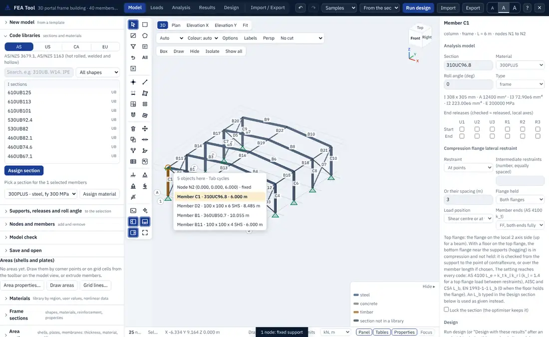
Object chooser. Where several objects lie under the pointer (a node, the members meeting at it and an area), a small list names them all. Tab cycles through the list and a click picks one.
Box and Crossing: drag a box. In Box mode, dragging left to right takes what lies fully inside and dragging right to left takes what the box touches. Crossing always takes everything the box touches. Ctrl-drag in the model view boxes without changing the tool.
Polygon: click the corners of a polygon, then the first corner or Enter; everything inside is selected.
Select by property picks every object with a given section, material, role (beam, column, brace), group, level, area type or support.
Select by coordinate range sets limits on X, Y and Z (a single value with a tolerance, or between two values, or no limit) for points, frames and areas, with the option that a frame or area counts only when all its points lie within the limits.
Previous selection brings back the selection before the last change. The selection filter limits picking to all objects, nodes only, members only or areas only. Clear empties the selection. Ctrl+A selects all members.
Hide, Isolate and Show all (H, I, Shift+H) act on the display, not the model: hidden objects are still analysed.
4.6 Editing
| Tool | What it does |
|---|---|
| Delete (Delete) | removes the selected members, areas and nodes; loads on them go too |
| Move | moves the selected nodes, or the nodes of the selected members and areas, by dx, dy, dz; attached members stretch and areas follow |
| Replicate (R) | copies the selection: linear (dx, dy, dz, n copies), radial (about a vertical axis through cx, cy, an angle per copy, n copies) or mirror (about a plane x, y or z = c); supports and loads can be copied with it |
| Divide | divides the selected members into n equal parts, or at their intersections with other members; member loads follow the parts |
| Merge nodes | merges nodes closer than a tolerance; members and areas are reconnected |
| Extrude | turns selected nodes into members, or selected members into areas, along a vector with n steps |
| Node coordinates table | lists the nodes with their coordinates for editing |
| Groups | names the selection as a group (members, nodes, areas) for later selection |
Nodes and members in the Model tab adds or removes nodes and members by typed coordinates and end nodes.
Every edit is one undo step. Groups and the defined grid are kept in the undo history and in the model file.
4.7 Roles and labels
Each member has a role: beam, column or brace. The role is set from the geometry when the member is drawn: a member whose rise is at least 0.9 of its length is a column, one whose rise is at most 0.1 of its length is a beam, and anything between is a brace. It can be changed in the properties panel. The role decides the design module, the default lateral restraint, the cracked-section modifiers of concrete members, and the groups used by the optimiser. Member and node labels are shown with Labels (L).
4.8 The model check
Model check in the Model tab, and Check the model in the Analysis tab, test the model before an analysis. The check lists, in plain words, members without a section or material, members of zero length, nodes on no member, parts of the structure with no support, end releases that leave a member free to spin, loads on objects that are not in the model, combinations that name missing cases, and degrees of freedom that no member reaches. It ends with a trial factorisation of the stiffness matrix, which names the node and direction of any mechanism. Every run button runs the same check first and will not start an analysis that cannot succeed. Chapter 19 lists the messages with their fixes.