Chapters
- 1 Getting started
- 2 The interface
- 3 Coordinate systems and conventions
- 4 Modelling
- 5 Materials
- 6 Sections
- 7 Supports, releases and modifiers
- 8 Loads
- 9 Load combinations
- 10 Meshing
- 11 Static analysis
- 12 Dynamic and seismic analysis
- 13 Results
- 14 Design
- 15 Scripting and the AI model builder
- 16 Import and export
- 17 Verification
- 18 Scope and limits
- 19 Troubleshooting
- 20 Glossary and notation
On this page
The objects you draw are not always the elements the engine solves. A frame member may be cut into several elements, and every area is divided into shell, plate or membrane elements. The FEA Tool does this at the start of each run, joins the results back to the members and areas you drew, and keeps the model itself unchanged. This chapter explains each kind of mesh, the settings that control it, the area elements, and the limits on mesh size.
10.1 Frame members
In a static analysis one frame element per member is exact: the element uses the exact (Timoshenko) shape functions for its end displacements, and the forces and deflections at the stations integrate the member loads exactly (Section 11.2). A member needs to be cut only when its interior matters to the stiffness or the mass:
- in a modal, response spectrum, time history or buckling analysis, where a member's own vibration or buckling between its ends counts. When no mesh is set, these analyses cut every member into 4 parts by default and say so;
- in a P-Delta analysis, where the moments between the ends are first-order on the end forces; cut slender compression members to capture the P-δ effect along them;
- in a nonlinear or pushover analysis with distributed loads or plasticity along the span (use segments in the analysis options).
Property modifiers, end offsets and mesh > Auto mesh sets the number of parts per member for the selected members. In the model file or a script, a mesh can also be given for the whole model, or as a largest element length in metres (mesh: {segments, maxLength}). The extra nodes are internal: they appear in the analysis model (Options > Show the analysis model) but not in the result tables, and the member results are joined back into one set of stations, with the joint station given once.
10.2 Members meeting at intermediate joints
A node that lies on the clear length of a frame member, within 1 mm (or for a member shorter than 1 m), cuts that member for the analysis. A beam framing into the middle of another beam is therefore connected even when the second beam was drawn as one member. Members that cross without a shared node are not connected unless you divide them at the crossing (Divide > At intersections with other members and nodes), or set mesh.atIntersections in the model file or a script, which cuts both members at a new shared node for each run. Trusses and cables are not cut. Results and design stay on the parent members, and the messages of the run list the members that were cut.
The nonlinear and pushover analyses keep members whole and ask you to divide such members with the Divide tool instead.
10.3 Area mesh
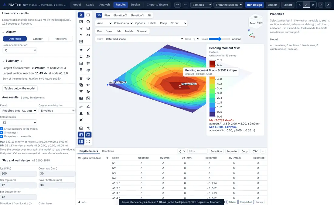
Every area is meshed when an analysis runs. Area properties sets the mesh of new or selected areas:
| Setting | Mesh |
|---|---|
| Automatic (default) | element size from the area and its surroundings (below) |
| Element size | squares of the given side, with mesh lines added through model nodes inside the area |
| Divisions | along edge 1-2 and along edge 2-3 of a quadrilateral; gives one element |
| Triangles | each quadrilateral split in two |
Automatic mesh. The element size is
where is the shorter span of the area, is 1 m (or the maximum you give) and is the largest automatic size in the model. Mesh lines are placed through every model node inside the area (columns, point supports, nodes with point loads), and graded lines at and are added on both sides of supports, springs and columns, where the moments change fastest.
Shapes. A convex quadrilateral with corner angles between 15° and 165° is meshed as a structured grid. Other areas (more than four corners, sharp or re-entrant quadrilaterals) are cut into triangles by ear clipping, pairs of triangles are joined into quadrilaterals where the corner angles stay between 30° and 150°, and each part is meshed. Divisions are matched along shared edges, and a final pass makes the mesh conforming: any model node or mesh node lying on an element edge or inside an element becomes a node of that element.
Shared nodes. A generated point within of the model size of an existing node uses that node, and model nodes on an area edge get a mesh line through them. Two areas that share an edge therefore share the nodes along it.
Area geometry. Repeated points are dropped. A point on the straight line between its neighbours stays a mesh node on that edge. Points on one line, and edges that cross, are refused with a message that names the area.
10.4 Frame-edge matching
A beam along the edge of a slab, or along a mesh line inside it, must share nodes with the slab to act with it. When areas are meshed, frame-edge matching (always on unless the model file sets mesh.matchFrames to false) cuts every frame member that has area mesh nodes lying on it, so that the beam and the slab share those nodes. Edge mesh nodes reuse existing model nodes. The results of the cut members are joined back to the original members, and the run reports how many members and nodes were matched.
Without matching, a beam meets the slab only at its end nodes and the slab spans as if it were point-supported there. Leave matching on unless a study needs the slab and beam unconnected.
10.5 Area elements
| Area type | Quadrilateral | Triangle |
|---|---|---|
| Shell, thick | QM6 membrane + drilling + MITC4 bending (Mindlin) | CST + drilling + DKT |
| Shell, thin | QM6 membrane + drilling + MITC4 with the transverse shear strains held near zero (Kirchhoff) | CST + drilling + DKT |
| Plate | MITC4 | DKT |
| Membrane | QM6 | CST |
The membrane part of a shell of membrane thickness uses the plane-stress constitutive matrix
and the bending part, with bending thickness ,
where is the transverse shear stiffness of the Mindlin elements. The MITC4 element interpolates the transverse shear strains from the edge midpoints, which removes shear locking, so the thick element also works for thin plates. The thin-shell quadrilateral raises the transverse shear stiffness by a factor of 1000 to hold the shear strains near zero.
A shell node has six degrees of freedom, but plane stress gives no stiffness to the rotation about the normal (the drilling rotation). A penalty stiffness in the manner of Hughes and Brezzi ties that rotation to the in-plane displacement field, so a beam framing into a wall or slab at an angle has something to connect to. A plate element gives no in-plane stiffness, and a membrane none out of plane; those degrees of freedom are held where nothing else acts on them.
A quadrilateral whose corners do not lie in one plane is projected onto its mean plane and connected to its nodes by rigid offsets. When the offset exceeds 1 % of the square root of the element area, the run reports the warp.
Area results at nodes are the averages of the element corner values over the elements of the area (with the Gauss-point values of a quadrilateral extrapolated to its corners).
10.6 Node limit and mesh size
An analysis accepts up to 3,000 nodes, 6,000 members and 18,000 degrees of freedom (Chapter 18). Area meshes add nodes quickly: a 30 × 20 m floor at 0.5 m has 2,501 nodes. When the automatic mesh would take the model beyond 85 % of the node limit, the areas away from supports, springs and columns are coarsened first, then every automatic area, and the run says by how much the element size was enlarged. An element size or division count that you set yourself is honoured as given.
10.7 Choosing a mesh
- Start with the automatic mesh. Check the result by halving the element size of the area you care about: when the governing moment changes by less than a few per cent, the mesh is fine enough.
- Keep elements roughly square. Aspect ratios above about 4 degrade the stresses.
- Put mesh lines where loads and supports are: the automatic mesh does this for model nodes, so draw a node where a column or point load acts.
- Expect peaks at point supports and re-entrant corners to grow as the mesh is refined: the elastic solution is singular there. Design from the moment at the face of the support or averaged over a design strip, not from the peak at the node.
- Use the analysis model display to see the mesh and the members that were cut.