Chapters
- 1 Getting started
- 2 The interface
- 3 Coordinate systems and conventions
- 4 Modelling
- 5 Materials
- 6 Sections
- 7 Supports, releases and modifiers
- 8 Loads
- 9 Load combinations
- 10 Meshing
- 11 Static analysis
- 12 Dynamic and seismic analysis
- 13 Results
- 14 Design
- 15 Scripting and the AI model builder
- 16 Import and export
- 17 Verification
- 18 Scope and limits
- 19 Troubleshooting
- 20 Glossary and notation
On this page
The FEA Tool does not hold its own member checks. It sends each member, with its design actions, to the TensorNode design module that covers it (Steel Member, Beam-Column, Steel Column, Tension Member, Flexure, Column Interaction, Beam Shear, the timber modules and others), exactly as if you had filled in that module by hand, and collects the utilisation and the governing check. Slabs and walls modelled with areas are designed for reinforcement from the area forces. This chapter covers the hand-off to the modules, the design actions and member data, the batch design table, the section optimiser, the Design Expert, and the design of slabs, walls and circular columns.
14.1 The design workflow
- Run an analysis with the strength combinations: usually linear static with all combinations, or P-Delta for a sway-sensitive frame.
- Press Run design in the header (or Design with these results in the Results tab). Every member is matched to its module and designed for the envelope of the strength combinations.
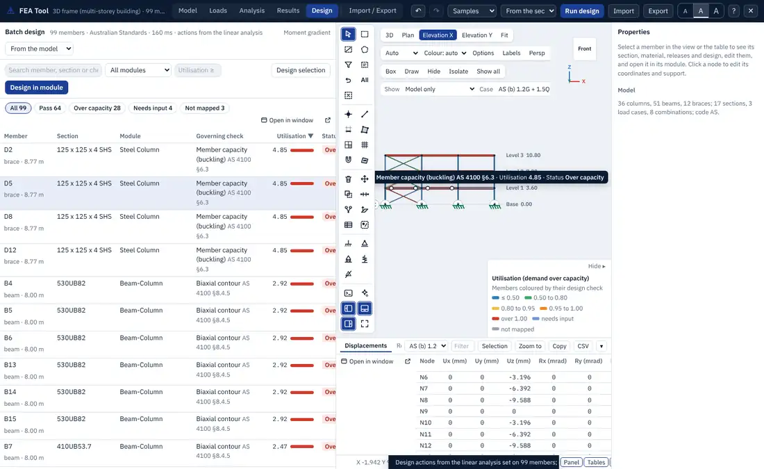
- Read the Batch design table in the Design tab: each member with its section, module, governing check, utilisation and status. The model view colours the members by utilisation.
- Fix what fails: change a section, add lateral restraint, enter a missing design input. The section optimiser and the Design Expert can do much of this for you.
- Run the analysis and design again until the sections used in the analysis are those that pass.
- Open in module (or Enter on a selected member) opens one member in its module, with every input filled, to read or print the full calculation with its clauses.
The design code is the one chosen in the header, or From the sections (the region of the section libraries used). Members in materials that no module designs (aluminium, prestressing tendon and user-defined materials) are analysed and listed as not designed, with the reason.
14.2 How members are matched to modules
| Member | Module |
|---|---|
| Steel beam with major-axis bending (AS) | Steel Member, with so the module reproduces the analysed moment for a simply supported span |
| Steel member with bending, otherwise | Beam-Column (W, rectangular and round HSS for US and CA; IPE, HE, SHS, RHS and CHS for EU; UB, UC, SHS, RHS and PFC for AS) |
| Steel member in compression only | Steel Column (an AS CHS column with bending goes to Compression Strut) |
| Steel member in tension only | Tension Member |
| Steel member in tension with bending | Beam-Column and Tension Member |
| Concrete column | Column Interaction (circular columns: Section 14.9), with Beam Shear |
| Concrete beam | Flexure, with Beam Shear |
| Timber member | the timber member or column module of the code |
A section from a frame section form (a box or pipe with catalogue dimensions, for example) is designed as the matching catalogue section where one exists. A concrete section takes its dimensions, bars and role from its form or its name.
Only the analysed actions govern. A module that derives an action from its own inputs (such as the AS Steel Member, which derives from ) has that derived check set aside and replaced by a check of the analysed action against the same capacity function. Torsion and minor-axis shear from the model are reported in the notes; no module checks them. A timber member with shear in a module that has no shear input is marked Needs input.
14.3 Design actions and moment gradient
The design actions of each member are the envelope of the strength combinations of the analysis shown: at every station the largest and smallest , , , , and , each taken independently, which is conservative. With load patterns only (no combinations), the envelope of the patterns is used and the table says so.
Moment gradient. By default (From the model), the factor for lateral-torsional buckling is computed from the moment diagram of the combination with the largest major-axis moment, over the critical segment between restraints:
For AS 4100 (Eq. 5.6.1.1(2)), with the largest moment in the segment and , , the moments at its quarter points,
For AISC 360 (Eq. F1-1), with , , the moments at the quarter points,
For CSA S16 (13.6),
For EN 1993-1-1 the end moment ratio of a linear diagram is passed, from which the module takes and ; for a curved diagram is used and the row says why.
A moment between two stations is interpolated only where no load acts between them. If the stations do not give the quarter points, the factor stays 1.0 and the row says why. Uniform (1.0) turns the gradient off.
14.4 Lateral restraint and effective length
The properties panel of a member has a Compression flange lateral restraint section, saved with the model:
| Setting | Choices |
|---|---|
| Restraint | none, at points (a number of equally spaced restraints or a spacing), continuous (a floor or deck holding a flange) |
| Flange held | top, bottom or both; the top flange is on the local +2 side |
| Other flange held at | the spacing of restraints (fly braces) to the other flange, 0 for none |
| Other flange in compression checked over | support to the point of contraflexure, or the member length |
| Load position | at the shear centre or at the restraints, or on the top flange |
| Member ends (AS 4100 ) | FF, FP or PP |
Each sign of the major-axis moment is designed separately, so the flange in compression and its unrestrained segment go to the module. For AS 4100 the effective length is
with from the end restraints and the section (Table 5.6.3), for a load on the top flange between restraints and ; with axial compression the Beam-Column module is run for the in-plane check with and for the out-of-plane check with . For AISC 360 and CSA S16 the unbraced length goes to the module with or from the segment's diagram (1.0 when the segment has both signs); for EN 1993-1-1 goes with . A fully restrained flange is passed as 0.25 m for AS, US and CA and as prevented for EN.
In hogging regions with only the top flange held, the bottom flange is checked from the support to the point of contraflexure, as a segment free at that point with a moment factor of 1.0. An typed in the design section of the member is used as given. Lock the section keeps the member's section through the optimiser and the Design Expert.
14.5 The batch design table and design inputs
The Batch design table lists every member with its role and length, section, module, governing check with its clause, utilisation and status:
| Status | Meaning |
|---|---|
| Pass | utilisation at most 1.00 |
| Over capacity | utilisation above 1.00 |
| Needs input | the module needs a value the model does not give (for example a bar layout or a timber shear input) |
| Not mapped | no module covers the member (material, shape or actions) |
Filter by status, module, text or utilisation, and sort by any column. Hovering over a row marks its member; clicking selects it. Design selection designs only the selected members. Colour: Utilisation in the view toolbar colours the members in bands (up to 0.50, 0.50 to 0.80, 0.80 to 0.95, 0.95 to 1.00, over 1.00), with needs input and not mapped in their own colours.
Design inputs lists the values the member checks assumed and lets you change them for the selected members: the concrete strength, cover, bar and tie diameters and bar count of concrete members, and the effective lengths , and . Members whose sections were drawn, and models with areas, are handled without stopping the batch: each member that cannot be designed says why.
Auto-select lists (Section 6.8) are resolved here: each member given a list is designed to the lightest section of the list that passes, the analysis is run again with those sections, and the cycle repeats until the analysis and design sections agree.
14.6 Section optimiser
Design > Optimise sections sizes the steel members for least mass. Each pass:
- analyses the model with the engine;
- designs every member in its module;
- for each group of alike members (same role, section, length, restraint setting, level and applied load, or each member alone), picks the lightest section of the same series (or shape, or a named series) in the code library whose utilisation is at most the target (default 0.95) and, for beams, whose deflection under the service combinations is at most span/250 (or the limit set), with slenderness at most 200 (300 in tension);
- analyses again, because the stiffness has changed.
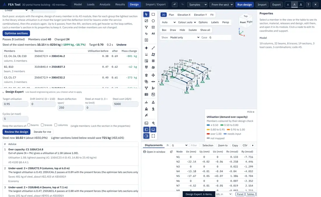
The passes repeat until no section changes, up to 6 passes. In passes 1 to 3 a group may get lighter or heavier; from the 4th, sections only get heavier, so the loop settles. Concrete and timber members are not changed, and locked members keep their sections. The whole run is one undo step; Accept keeps it and Undo restores the sections. The report lists, for each group, the old and new sections, the utilisation before and after and the change in mass, the members that remain above the target with the reason, and the total steel mass before and after.
14.7 Design Expert
Design > Design Expert is a rule-based advisor. Review the design runs the linear analysis and the design of every member, then lists advice ranked by consequence, each item with its reason, the numbers and the clause:
- instability (a mechanism or a buckling factor below 1);
- over capacity, with the remedies that apply: a heavier section with the lightest that passes, lateral restraint, a minor-axis brace, fixed bases;
- storey drift and beam deflection beyond their limits;
- torsional irregularity, when a seismic analysis has reported it;
- slender members and unbraced beams;
- under-used members, with the lighter section that passes, the steel saved and an estimate of the cost at the rate you give;
- missing load combinations, and members that no module designs.
Each item has Apply, which makes the change as one undo step and runs the analysis and design again.
Iterate for me repeats the sequence until the targets are met or the cycles run out (5 by default): analysis, design, drift sizing of the columns and of the beams at their tops, and the section optimiser. A live log shows each step; Stop ends it, and Accept or Undo keeps or reverses the whole sequence. Members of the roles you tick (beams, braces, columns) and locked members keep their sections.
The default storey drift limits are for AS and CA, for US and for EU in multi-storey buildings, and for single-storey buildings, checked under the service combinations with wind (or the wind patterns alone when there are none). The beam deflection limit defaults to span/250. All are inputs of the panel, together with the target utilisation, a limit on the total steel mass and the steel cost per tonne.
14.8 Slab and wall design
Results > Slab and wall design computes the reinforcement that the shells, plates and membranes need, at every node of every area and for every strength combination, to AS 3600-2018, ACI 318-25, EN 1992-1-1:2004 (recommended values) or CSA A23.3-19. The inputs are the yield strength of the steel, the cover and bar diameter at the top and bottom faces, the angle of reinforcement direction 1 from local axis 1, which direction is the outer layer, whether the area is a slab or a wall (found from its normal unless set), and for AS 3600 the support of the slab for the minimum steel (AS 3600 9.1.1). The defaults are those of the code (for AS: MPa, cover 30 mm, 12 mm bars). An area can override the settings of the model.
Forces in the reinforcement directions. The area forces are turned from local axes 1-2 to the reinforcement directions at angle :
with , , and likewise for the membrane forces.
Wood-Armer moments (Wood 1968; Armer 1968). With positive for tension at the bottom face, the design moments for the bottom reinforcement are
If , then and ; if , then and ; if both are negative, no bottom steel is needed. The top reinforcement follows with the signs reversed: and , with the same rule for positive values. A pure twisting moment therefore needs in both directions on both faces, and a one-way strip keeps its moment.
Membrane forces use the yield conditions for an orthogonal mesh of Clark (1976) and Nielsen, with tension positive:
with the same rule when one of them is negative ( for the other). The concrete between the bars carries the compression in the general case. Half of the membrane steel goes to each face.
Steel area. For each face and direction, the flexural steel per unit width follows from the rectangular stress block of the code at the effective depth of that layer (direction 1 outermost unless set otherwise):
where is the force per unit area of the stress block (for example for ACI 318), the design steel stress and the resistance factor (or the partial factors of EN 1992-1-1). The membrane steel is added, and the minimum steel of the code governs where it is larger: for slabs on a face that needs tension steel, for walls on both faces with half the total ratio each.
Shear. The transverse shear is compared with the one-way shear strength of the code without shear reinforcement, and the ratio is reported.
Results. Contours of the required steel (mm²/m) at the top and bottom in directions 1 and 2 and of the shear ratio, either enveloped over the strength combinations or for one of them, with the legend and the value under the pointer; a report section with the design basis and a summary per area; and a table of every node. The steel areas are the theoretical amounts at each node: choose bars for design strips and detail them to the code, considering the averaging of peaks at point supports.
14.9 Circular concrete columns
A circular reinforced concrete member is designed by strain compatibility, with bars equally spaced on a circle and the rectangular stress block on the compressed circular segment, using the code factors of the rectangular Column Interaction module. The interaction curve gives the axial and moment capacities with their strength reduction factors, the squash load and the balance point, and the design takes the axial force, the resultant moment and the effective length of the member.